Tech Tips

Home / Tech Tips

Here at Avanceon, we’ve been developing solutions for our customers for a long time. And in the process, we’ve run into – and solved – many “interesting” technical challenges. We’ll share some of the more generally applicable ones on this page: after all, if we already have a solution, why should you have to develop your own?


Beware Asynchronous Operation!

Full Info
Issue: Transient data is read by an Ethernet client during array copy
 
In the PLC code in Figure 1 below (ControlLogix converted from PLC5), the rung copies the alarm array (N750) into another array (MsgBoard), then zeroes out all or portions of the array based on process conditions. This can cause problems.


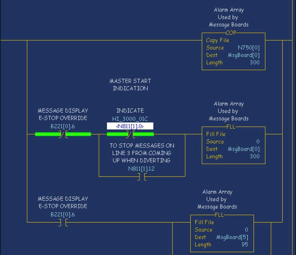
Figure 1. PLC code with rung copy of alarm array

 
The rung executes sequentially, so by the time the rung completes execution, the MsgBoard array has the correct contents. However, the Ethernet communication to the PLC is not synchronized to the PLC program scan, which means that periodically, the Ethernet client reads transient data because the rung hasn’t finished executing when the data is read. 
 
This can happen more frequently than one would expect: in the case of the example in Figure 1, about once in every 15 minutes, which can cause considerable problems.
 
Solution:
If multi-step operations need to be done on data being read by an external client, use buffer tags and move the result to the ‘actual’ tag when the calculations are complete. This ensures that the tags being read by the external system will never have incorrect intermediate values.


Forcing Unsupported Conversions in Studio 5000

Full Info
Issue:
 
There are situations in which the Rockwell Logix/Studio 5000 development tool does not allow you to make changes to modules in the project tree after they’ve been created (such as Ethernet modules and certain processors). A typical example is where you have had to create your code before design teams have finalized their choice for processor type: given the dependency of code on processor selection, sometimes you are “too far down a one-way road” to make a change and convert from, say, an L81E to an L71 processor.
 
Similarly, maybe you assumed the use of ENBT Ethernet modules, only to find out later that EN2T modules have been purchased. If you’ve created a large number of client connections like drives, I/O racks, and other devices under that ENBT in the project tree, you’ll be faced with deleting and re-adding them under the EN2T.
 
Solution:
There is, however, a way in which you can make the process easier, though you will not find it in any instruction manual. What you must do is export the entire program to an L5K file, make the required changes manually in the text file, and then re-import the code to Studio5000 as a new program.
 
The specific steps will depend on what you need to do, but here is a process for changing code for an L81E processor to code for an L71:
 
1. Export the L881E program to an L5K file
2. Edit the L5K file with a text editor.

a. Under “CONTROLLER”, change “L81E” to “L71”

b. Under “MODULE Local” change “L81E” to “L71”

c. Under “MODULE Local” change ProductCode to 92

3. Save the L5K file, and then open it with Studio5000.

a. You may receive warnings from Studio5000, but you will be able to bypass them. Studio5000 will accept the change to L71.

 
Caution: As this is not a “standard” solution, please make sure you check your code carefully to make sure all necessary changes have taken place successfully.
 
If you need to make a different change, like in the Ethernet example, it is simplest to create a “dummy” module of the type you need, and then use that as a template when making changes in the L5K file.


Bulk Delete FactoryTalk View Tags

Full Info
Issue: Bulk Renaming in the FactoryTalk View SE and ME tag Database
 
A useful feature of the FactoryTalk View SE and ME HMI applications is their ability to export the tag database to CSV files, edit them, and re-import them. This feature allows you to add new tags or make changes to items such as descriptions or PLC addresses. However, there is no built in way to delete or rename tags in bulk; if you try to change the name of a tag in the CSV, then import it, you’ll end up with two tags rather than one renamed tag.
 
You can work around this limitation by exporting the entire database to CSV, deleting or editing the appropriate tags, and then replacing the source tag database with a new, empty one created from scratch. Then import the CSV with your changes.
 
Solution:
You can make bulk changes/additions by executing the following steps:
 
• Export the tags and alarms to a CSV file, and make the required changes
• Create a new, empty FTView project and close it immediately.
• Using Windows Explorer, go to the \Tag folder of the project you’re deleting or otherwise changing tags from and delete all the files in the folder
• Copy the \Tag folder contents from the new, empty project and rename them to match the filenames you deleted
• Import the CSV files from step 1 into your project


SuiteLink Communications Troubleshooting

Full Info
Issue: Difficulty troubleshooting communications between a DDE/SL DI object deployed to an AOS and an instance of FSGateway on a remote PC.
 
Solution:
SLSPing
Typically, you open command prompt and execute “ping” to test general network communication between the machine you’re on and the hostOrIP machine you’re trying to see. If it succeeds (gets a response from the remote PC) but your DDE/SL objects are still not talking properly, try SLSPing.
 
The syntax is “slipping “.
 
For example, if you had a machine called AOS and you were trying to communicate with a machine called PC that has FSGateway running on it:

– From AOS, open command prompt and execute the command “ping PC”

– From AOS, execute the command “slapping PC FSGateway”.

(If you cannot ping the PC, you have some general network communication issue and that will need to be resolved before trying slsping.)
 
If you can ping the PC but the slsping command fails, make sure that whatever application you’re talking to (in this example case, FSGateway) is actually running and make sure there are no firewalls blocking communications between the machines. Once you resolve any issues and can both ping and slsping the SuiteLink application, your DI/OI objects should communicate without issue.
 
ProTip:
Even if the firewall is “off”, check for Antivirus software…


Problems adding graphics to an InTouch app

Full Info
Issue: Error message when adding an Orchestra Graphic popup to your Intouch application.
 
You create an Orchestra Graphic popup for your application, test it on the Galrep, then deploy your application only to get this:


Why does this happen and how can you fix it?
 
This happens because deploying an InTouch app will only include the graphics that are embedded in windows within the application. A popup is not an embedded graphic, so it does not get deployed with the rest of the application.
 
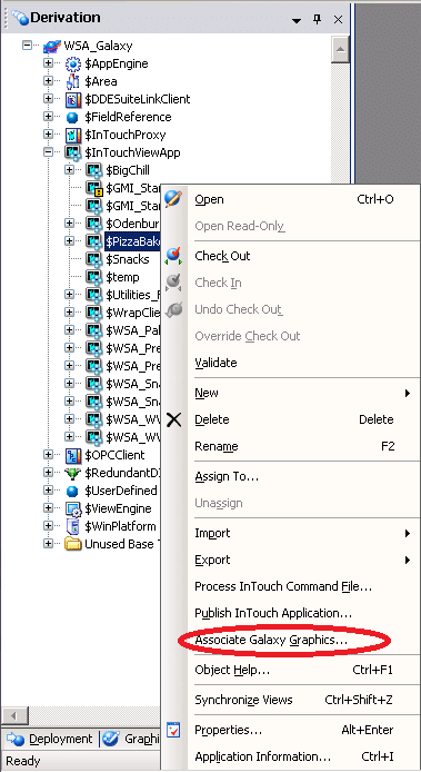
To fix this, most sources will tell you that you need to “Associate Galaxy Graphics” with the Intouch application. From the Orchestra Graphics User Guide: “This option sets the InTouch View Application to include all the graphics that have been configured in the Galaxy whether they have been embedded in the application or not.” To do this right click on the application in the Galrep and select “Associate Galaxy Graphics”:


While this works like a charm, it has one major drawback. To perform this operation you must un-deploy all instances of the application. In a production environment this is usually impractical.
 
Solution:
To avoid having to un-deploy your app, you can simply embed your graphic into your app. Once the graphic is embedded in a window, it will be included with the deployment. Embedding a popup doesn’t always fit into most screen layouts, so it is best to find an inconspicuous location. You can do this by creating a new window solely for this purpose, the window is never viewed in the application. After that check in the app in, deploy like normal, and you’ll be off to the races.


Running InTouch on Multiple Monitors

Full Info
Issue: Configuring HMI visualization software to run on multiple monitors
 
Solution:
It is possible to run InTouch HMI visualization software on multiple monitors with two alternatives:
Essentially “trick” Microsoft Windows into treating the two monitors as a single monitor with the combined resolution of the multiple displays.
Edit three .ini files to configure multiple monitor usage in an extended desktop setup.

 If you choose the first option, you must have graphics cards and drivers that support dual displays. Beyond this, no additional configuration should be required.
 
If you choose the second option, using extended desktop mode, carry out the following steps on the node that the InTouch WindowViewer will be running:
Run notepad as Administrator
Open the file C:\Windows\win.in
Locate the [InTouch] section and add three parameters
 MultiScreen=1
MultiScreenWidth=XXXX (total combined screen width)
MultiScreenHeight=XXXX (total combined screen height)
Save and close the file
Add the same three parameters to the [InTouch] section of two more files:
C:\Program Files (x86)\ArchestrA\Framework\Bin\\InTouch.ini
C:\Users\\AppData\Local\Wonderware\win.ini 

Note: If one or more of the directories do not exist, make sure you have the correct software components installed for InTouch and run the InTouch application at least once before carrying out the steps above.
 
If you’re in extended desktop mode and you’ve added these parameters to the three files, WindowViewer should now fill in all the monitors as you’ve configured it.


Manage InTouch App Warning

Full Info
Issue: If you delete an embedded ArchestrA graphic from a managed InTouch application, you will receive a message that items are missing from the galaxy, but you will not be notified on the template about which screens are affected or which screens reference the deleted item(s). The warning display will be similar to the following (Fig. 1)


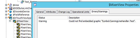
Figure 1 – Notification of Missing Graphic

 
Solution:
To find which screens are affected:
Open the screens in WindowMaker one at a time, with the SMC log open.
When a screen referencing the missing graphic opens, a log message similar to the following will appear (fig. 2):


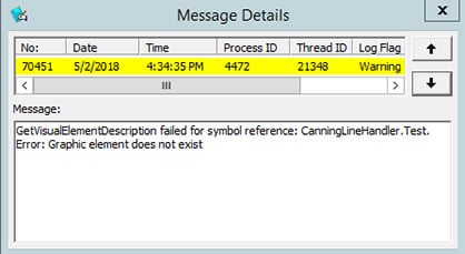
Figure 2 – Log Message

While this method does not provide an exact position for the missing graphic, it will at least indicate which screen is affected.
 
Be sure to consider whether the missing graphic is off-screen.


Avanceon is happy to offer these suggestions for resolving common issues. Note that since every installation is different, they may not address or be appropriate for your particular situation. We know they’ve worked for us – but use them at your own risk.